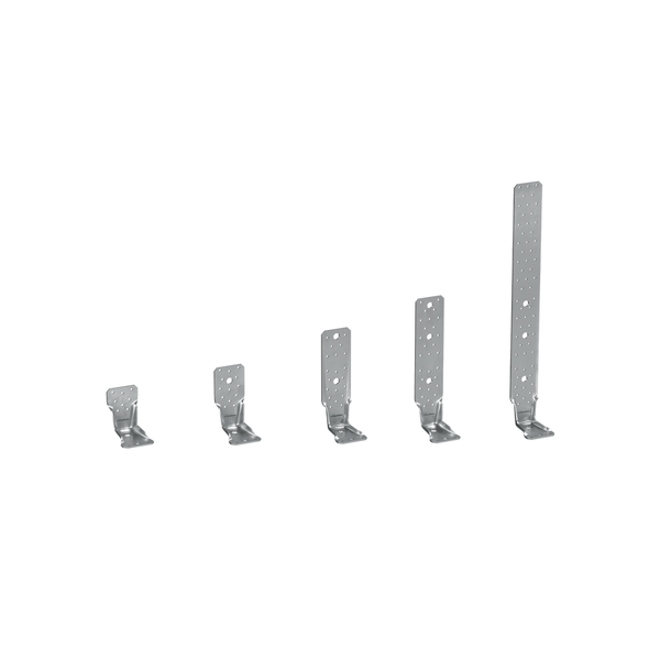
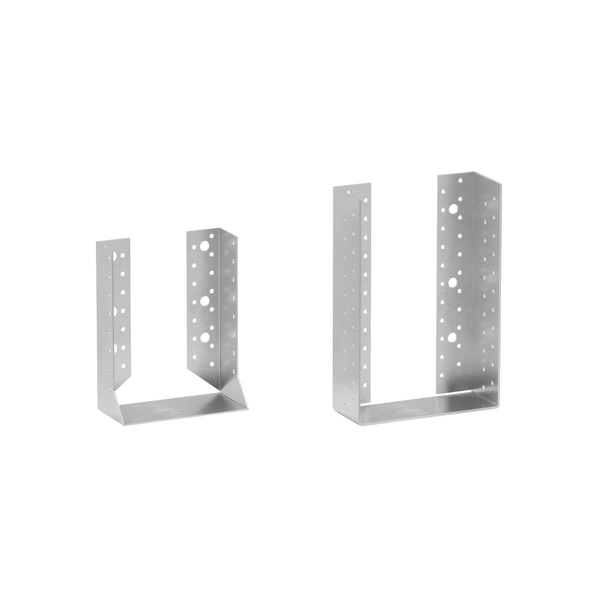
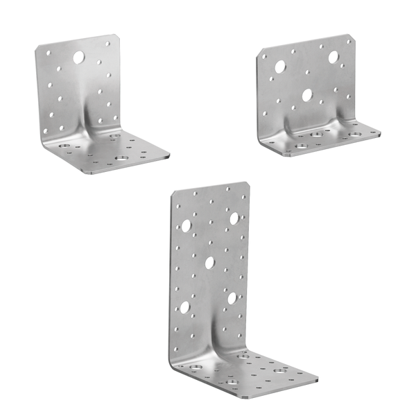
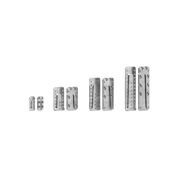
Most timber connections carry load downwards. Hold-downs and tensile plates do the opposite job: they stop the structure lifting, sliding, or tipping over. In a tall timber wall, a wind-loaded frame, or a cross-laminated timber building, these connectors anchor the structure against uplift and overturning, and they are often the connection that decides whether the whole assembly stands up under lateral load. This guide explains what they do, the main types, and how they are designed and fixed.
The forces hold-downs resist
When wind pushes on a building, or a timber shear wall resists lateral load, the result is a turning effect. One edge of the wall is pushed down while the other is pulled up, trying to lift the wall off whatever supports it. That uplift, and the overturning moment behind it, has to be carried into the structure below, floor to floor and ultimately into the foundation. A hold-down is the connector that takes that tension and ties the wall down. Without it, the panels can be perfectly strong and the building still fails at the junctions under lateral load.
Plates, hold-downs, and tensile connectors
| Connector | Job | Where it sits |
|---|---|---|
| Hold-down | Resists tension and uplift, tying a wall or panel down | Wall-to-floor and wall-to-foundation, at panel ends and openings |
| Tensile plate | Carries tension across a joint between panels or members | Panel-to-panel and timber-to-timber where uplift transfers |
| Angle bracket | Resists shear, the sliding component of lateral load | Base of walls, working alongside hold-downs |
Hold-downs and shear brackets work as a pair. The hold-down takes the tension and uplift; the angle bracket takes the shear. Designing one without the other leaves half the lateral load path unresolved. Tensile plates extend the same principle to joints between members, carrying tension across a connection that would otherwise pull apart.
How they are designed
A hold-down connection is checked on three fronts, and the weakest governs. First, the steel connector itself must carry the tension. Second, the fixings into the timber, usually a dense pattern of structural screws, must transfer that tension into the panel without the screws withdrawing or the timber splitting. Third, the anchor into the supporting structure, a bolt or chemical anchor into concrete at the base, must hold the whole assembly down. A hold-down rated for a high load is only as good as the screws feeding it and the anchor beneath it.
Design reality: the published capacity of a hold-down assumes a specific screw pattern and a specific anchor. Change the fixings and you change the capacity. The connector, the screws, and the anchor are one system, not three separate choices.
Fixing for full capacity
- Fill the full screw pattern the connector specifies, using the stated screw type and length, because the tested capacity depends on it.
- Position hold-downs at panel ends and either side of large openings, where uplift concentrates.
- Keep hold-down locations stacked floor to floor where possible, so the tension load path runs cleanly to the foundation.
- Match the base anchor to the substrate, and let the anchor capacity, not just the plate, inform the design.
The role of assessed products
As with other structural timber connections, the design values for plates and hold-downs come from European Technical Assessments, which let an engineer verify the connection to Eurocode 5. The assessment ties the connector to its fixings and gives the characteristic tensile capacity you design against. Using assessed connectors, fixed exactly as the assessment requires, is what makes the uplift and overturning checks valid rather than assumed.
Specifying plates and hold-downs with TimbA
TimbA Systems supplies structural plates and hold-downs from stock alongside the engineering to design them in. Our plates, hold-downs, and angle brackets cover tension and shear connections for timber frame and CLT, fixed with the structural screws and anchors their capacities depend on. Our engineering team can size the hold-down, screw pattern, and base anchor as one connection to Eurocode 5, and the approach ties directly into wider CLT connection design. The fastener calculator gives screw and anchor quantities for our connectors.
Design the connector, its screws, and its anchor as one system, fix it as specified, and the structure stays tied down under the loads that try to lift it.