In a cross-laminated timber building, the panels rarely fail. The connections do the hard work, and they are where most of the engineering risk, cost, and programme time actually sits. Getting CLT connection design right under Eurocode 5 is what turns a stack of panels into a stable, code-compliant structure. This guide explains how those connections are engineered in the UK, what the code does and does not cover, and where the practical decisions are made.
Why connections govern CLT design
CLT panels are strong and stiff in plane, so the limiting factor on a project is almost always how loads pass from one panel to the next, and from the superstructure into the foundations. Wind uplift, seismic-style lateral loads, diaphragm shear, and overturning all resolve through the connections. A panel that is more than adequate on paper can still fail a design check because the hold-down or the screwed joint feeding it cannot carry the demand.
That is why connection design, not panel sizing, is usually the first thing an experienced timber engineer looks at. It drives the hardware schedule, the screw counts, and a large share of the build cost.
Eurocode 5 and CLT: the design basis
Structural timber in the UK is designed to Eurocode 5, formally EN 1995-1-1, read with the UK National Annex. Section 8 of the code sets out the rules for connections made with metal dowel-type fasteners, including screws, dowels, bolts, and nails. Capacities for laterally loaded fasteners come from the European Yield Model, often called Johansen's theory, which predicts the failure mode from the geometry and the embedment strength of the timber. Axially loaded screws are checked separately for withdrawal and head pull-through.
Every design value follows the same form. The characteristic resistance is modified by kmod, which accounts for load duration and service class, then divided by the partial factor for the material or connection. Service class and load-duration class therefore feed directly into the numbers, and a connection that works for a permanent load may not work for a short-term wind case, or the reverse.
Key point: the 2004 edition of Eurocode 5 predates widespread CLT use and gives no explicit CLT connection rules. Designers rely on European Technical Assessments for both the panels and the fasteners, alongside the second-generation Eurocode 5 now bringing CLT into the code directly.
The main CLT connection types
Most CLT structures are built from a small family of connection details, each doing a specific job.
| Connection | Job it does | Typical hardware |
|---|---|---|
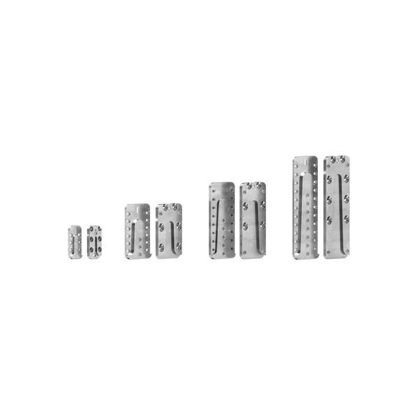
| Panel-to-panel joints | Transfer in-plane and diaphragm shear between adjacent panels | Self-tapping screws, often full-thread, into a spline or half-lap |
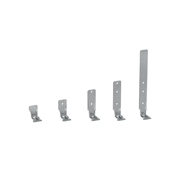
| Angle brackets | Resist shear at wall-to-floor and wall-to-foundation junctions | Shear brackets fixed with screws or anchors |
| Hold-downs and tensile plates | Resist uplift and overturning, anchoring walls against tension | Hold-down plates such as the WHT family |
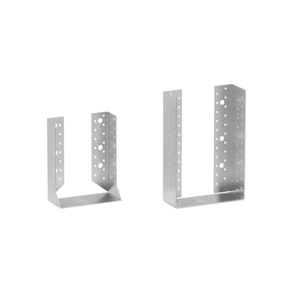
| Beam and joist connections | Support floor and roof members into walls or beams | Concealed and face-fixed beam hangers |
| Reinforcement | Carry concentrated loads and prevent splitting at supports and notches | Long full-thread screws installed at an angle |
Designing screwed connections
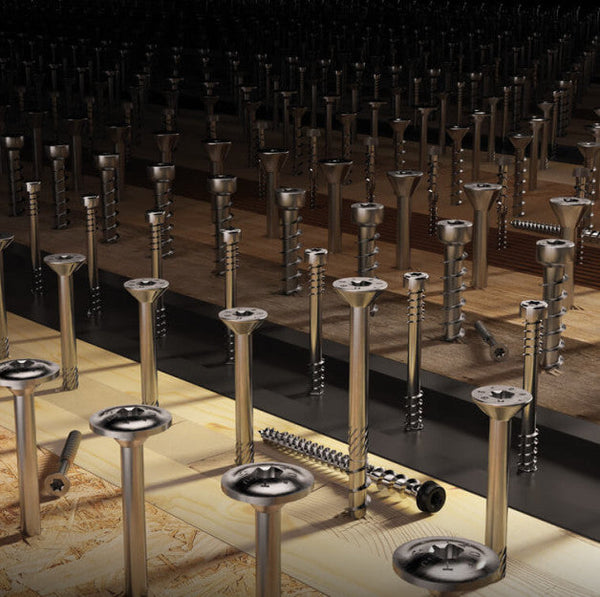
Screws carry most of the load in modern CLT detailing because they are fast to install and predictable to design. Two checks dominate. For laterally loaded screws, the yield model gives the lateral capacity per fastener, which is then multiplied across the group with an effective-number rule so that a long row of screws does not count at full value. For axially loaded screws, withdrawal capacity depends on the embedded thread length, the screw diameter, and the panel density.
Spacing and edge distances are not optional detailing. They are part of the capacity calculation. Place screws too close and the timber splits before the fastener reaches its rated load; place them too near an edge and the characteristic values no longer apply. CLT adds a further layer, because fixing into the narrow edge of a panel behaves differently from fixing into the face, and the governing ETA sets specific rules for each case.
Practical note: the right screw count is a balance, not a maximum. Enough fasteners to carry the demand, spaced correctly, beats a dense pattern that risks splitting and wastes labour.
Where ETAs come in
Because Eurocode 5 does not yet give complete CLT and screw rules in the body of the code, the characteristic values you design with come from European Technical Assessments. An ETA is the document that turns a manufactured product into something an engineer can put numbers to. For structural screws it provides withdrawal parameters, head pull-through, and tensile capacity; for CLT panels it gives the strength and stiffness properties. Designing with assessed products, rather than generic assumptions, is what keeps a CLT connection both safe and economical.
Detailing that saves time on site
- Decide the connection strategy before the panels are cut, so fixing zones and access are designed in, not retrofitted.
- Keep hold-down and bracket positions consistent floor to floor where you can, which simplifies the screw schedule and the installer's work.
- Specify screw lengths that suit the panel thickness and the timber below, allowing for the full thread engagement the withdrawal check assumes.
- Coordinate connection zones with services early, because a clash discovered on site usually ends in a weaker improvised fix.
How TimbA supports CLT connection design
TimbA Systems combines a UK-based structural engineering consultancy with the connection hardware to deliver it. Our engineering and design service works through CLT connections to Eurocode 5, from the panel-to-panel joints to the hold-downs and shear brackets, and translates the design into a buildable fixing schedule. We supply the matching hardware from stock, including structural plates, hold-downs, and angle brackets and a full range of structural timber screws, with mass timber sourcing when you need the panels too. For quick sizing, the fastener calculator gives screw and anchor quantities for our connectors.
If you have a CLT project on the board, talk to our engineering team early. The connection decisions made at concept stage are the ones that shape cost and programme all the way to completion.